14 KiB
C, pronounced I-squared-C, is a multi-controller, multi-peripheral protocol, where any connected device can act as a controller or peripheral, communicating over the I²C bus (the name for the communication system that transfers data). Data is sent as addressed packets, with each packet containing the address of the connected device it is intended for.
💁 This model used to be referred to as master/slave, but this terminology is being phased out due to its association with slavery. The Open Source Hardware Association has adopted controller/peripheral, but you may still encounter references to the old terminology.
Devices have an address that is used when they connect to the I²C bus, and this address is usually hard-coded on the device. For example, each type of Grove sensor from Seeed has the same address for its type—so all light sensors share the same address, all buttons share the same address (different from the light sensor address), and so on. Some devices allow you to change the address by adjusting jumper settings or soldering pins together.
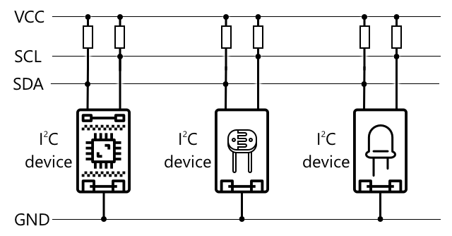
I²C uses a bus made of two main wires, along with two power wires:
| Wire | Name | Description |
|---|---|---|
| SDA | Serial Data | This wire is used for sending data between devices. |
| SCL | Serial Clock | This wire sends a clock signal at a rate set by the controller. |
| VCC | Voltage common collector | The power supply for the devices. This is connected to the SDA and SCL wires to provide their power via a pull-up resistor that switches the signal off when no device is acting as the controller. |
| GND | Ground | This provides a common ground for the electrical circuit. |
To send data, one device issues a start condition to indicate it is ready to transmit. It then becomes the controller. The controller sends the address of the device it wants to communicate with, along with whether it intends to read or write data. After the data has been transmitted, the controller sends a stop condition to signal that it has finished. At this point, another device can take over as the controller and send or receive data.
I2C Speed Modes
I2C has speed limits and operates in three different modes with fixed speeds. The fastest mode is High-Speed mode, which can reach a maximum speed of 3.4 Mbps (megabits per second), though very few devices support this speed. For example, the Raspberry Pi is limited to Fast mode at 400 Kbps (kilobits per second). Standard mode operates at 100 Kbps.
💁 If you're using a Raspberry Pi with a Grove Base Hat as your IoT hardware, you'll notice several I2C sockets on the board. These can be used to communicate with I2C sensors. Analog Grove sensors also use I2C with an ADC to convert analog values into digital data. For instance, the light sensor you used simulated an analog pin, but the value was transmitted over I2C since the Raspberry Pi only supports digital pins.
Universal Asynchronous Receiver-Transmitter (UART)
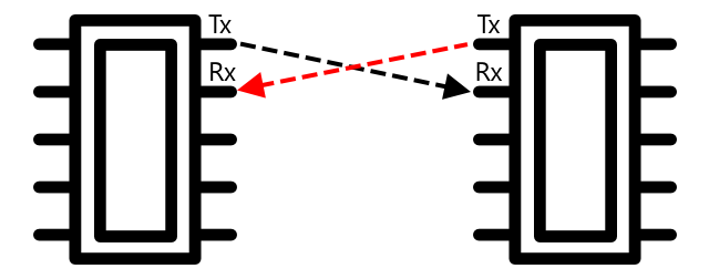
UART is a physical communication protocol that allows two devices to exchange data. Each device has two communication pins: transmit (Tx) and receive (Rx). The Tx pin of one device connects to the Rx pin of the other, and vice versa, enabling bidirectional communication.
- Device 1 sends data from its Tx pin, which is received by Device 2 on its Rx pin.
- Device 1 receives data on its Rx pin, which is sent by Device 2 from its Tx pin.
🎓 Data is transmitted one bit at a time, a method known as serial communication. Most operating systems and microcontrollers have serial ports, which are connections that can send and receive serial data and are accessible to your code.
UART devices operate at a specific baud rate (also called the Symbol rate), which determines the speed of data transmission in bits per second. A common baud rate is 9,600, meaning 9,600 bits (0s and 1s) are transmitted each second.
UART uses start and stop bits to frame data. A start bit signals the beginning of a byte (8 bits) of data, and a stop bit marks its end.
While UART speed depends on hardware, even the fastest implementations typically don't exceed 6.5 Mbps (megabits per second).
You can use UART over GPIO pins by designating one pin as Tx and another as Rx, then connecting these to another device.
💁 If you're using a Raspberry Pi with a Grove Base Hat as your IoT hardware, you'll find a UART socket on the board for communicating with sensors that use the UART protocol.
Serial Peripheral Interface (SPI)
SPI is designed for short-distance communication, such as between a microcontroller and a storage device like flash memory. It follows a controller/peripheral model, where a single controller (usually the IoT device's processor) communicates with multiple peripherals. The controller manages communication by selecting a peripheral and sending or requesting data.
💁 Similar to I2C, the terms "controller" and "peripheral" are recent updates, so you might encounter older terminology in some resources.
SPI controllers use three shared wires and one additional wire per peripheral. Peripherals use four wires in total:
| Wire | Name | Description |
|---|---|---|
| COPI | Controller Output, Peripheral Input | Sends data from the controller to the peripheral. |
| CIPO | Controller Input, Peripheral Output | Sends data from the peripheral to the controller. |
| SCLK | Serial Clock | Sends a clock signal at a rate determined by the controller. |
| CS | Chip Select | Each peripheral has its own CS wire, which the controller uses to activate the desired peripheral. |
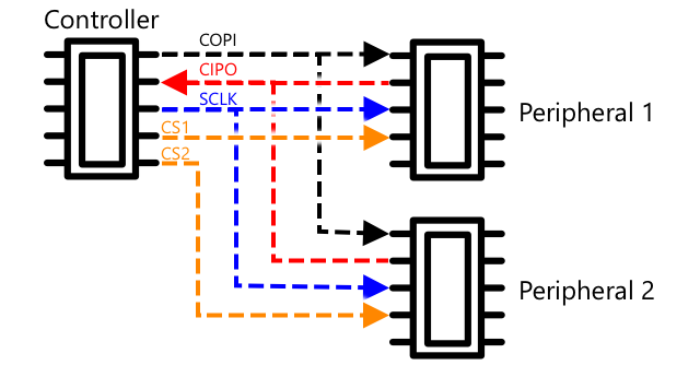
The CS wire activates one peripheral at a time, enabling communication over the COPI and CIPO wires. To switch peripherals, the controller deactivates the current CS wire and activates the CS wire for the next peripheral.
SPI is full-duplex, meaning the controller can simultaneously send and receive data from the same peripheral using the COPI and CIPO wires. A clock signal on the SCLK wire keeps the devices synchronized, eliminating the need for start and stop bits.
SPI has no defined speed limits, and implementations can often transmit several megabytes of data per second.
IoT developer kits frequently support SPI over GPIO pins. For instance, on a Raspberry Pi, GPIO pins 19, 21, 23, 24, and 26 can be used for SPI.
Wireless
Some sensors communicate using standard wireless protocols like Bluetooth (especially Bluetooth Low Energy, or BLE), LoRaWAN (a Long Range low-power networking protocol), or WiFi. These protocols enable remote sensors that aren't physically connected to an IoT device.
For example, commercial soil moisture sensors measure soil moisture in a field and transmit the data over LoRaWAN to a hub device. The hub processes the data or sends it over the Internet. This setup reduces power consumption and eliminates the need for extensive WiFi networks or long cables.
BLE is commonly used in advanced sensors like fitness trackers. These devices combine multiple sensors and transmit data to an IoT device, such as your phone, via BLE.
✅ Do you have any Bluetooth sensors at home, school, or on your person? Examples include temperature sensors, occupancy sensors, device trackers, and fitness devices.
A popular protocol for commercial devices is Zigbee. Zigbee uses WiFi to create mesh networks, where each device connects to as many nearby devices as possible. This forms a web-like network. When a device needs to send a message to the Internet, it forwards the message to the nearest device, which relays it to others until it reaches a coordinator and is sent online.
🐝 The name Zigbee refers to the waggle dance performed by honeybees when they return to their hive.
Measure the Moisture Levels in Soil
You can measure soil moisture using a soil moisture sensor, an IoT device, and a houseplant or a nearby patch of soil.
Task - Measure Soil Moisture
Follow the appropriate guide to measure soil moisture with your IoT device:
Sensor Calibration
Sensors measure electrical properties like resistance or capacitance.
🎓 Resistance, measured in ohms (Ω), indicates how much a material opposes the flow of electric current. When voltage is applied, the current depends on the material's resistance. Learn more on the electrical resistance Wikipedia page.
🎓 Capacitance, measured in farads (F), is the ability of a component or circuit to store electrical energy. Learn more on the capacitance Wikipedia page.
These raw measurements aren't always useful. For instance, a temperature sensor might give a reading of 22.5 KΩ, which isn't intuitive. Calibration converts these values into meaningful units by matching the sensor's readings to known quantities.
Some sensors are pre-calibrated. For example, the temperature sensor you used earlier was calibrated to return measurements in °C. During manufacturing, the sensor is exposed to known temperatures, and its resistance is measured. This data is used to create a formula that converts resistance (Ω) to temperature (°C).
💁 The formula for calculating resistance from temperature is called the Steinhart–Hart equation.
Soil Moisture Sensor Calibration
Soil moisture is measured using either gravimetric or volumetric water content:
- Gravimetric: The weight of water per unit weight of soil, measured in kilograms of water per kilogram of dry soil.
- Volumetric: The volume of water per unit volume of soil, measured in cubic meters of water per cubic meter of dry soil.
🇺🇸 In the U.S., these can be measured in pounds or cubic feet due to consistent unit ratios.
Soil moisture sensors measure electrical resistance or capacitance, which varies with both soil moisture and soil type. Calibration involves comparing sensor readings to scientifically measured values. For example, lab-calculated gravimetric soil moisture values can be used to calibrate the sensor, aligning its readings with actual moisture levels.

The graph above illustrates sensor calibration. Voltage readings are taken from a soil sample, which is then analyzed in a lab. The lab measures the soil's wet and dry weights to calculate moisture content. These data points are plotted, and a line is fitted to the graph. This line is then used to convert sensor readings into accurate soil moisture measurements.
💁 For resistive soil moisture sensors, voltage increases as soil moisture rises. For capacitive sensors, voltage decreases with increasing soil moisture, resulting in a downward-sloping graph.

The graph above shows how a voltage reading from a soil moisture sensor can be used to determine the actual soil moisture level.
This method allows farmers to take a few lab measurements for calibration and then use IoT devices for rapid soil moisture monitoring.
🚀 Challenge
Resistive and capacitive soil moisture sensors have distinct differences. What are these differences, and which type (if any) is better for farmers? Does the answer vary between developing and developed countries?
Post-Lecture Quiz
Review & Self-Study
Learn more about the hardware and protocols used by sensors and actuators:
Assignment
Disclaimer:
This document has been translated using the AI translation service Co-op Translator. While we aim for accuracy, please note that automated translations may include errors or inaccuracies. The original document in its native language should be regarded as the authoritative source. For critical information, professional human translation is advised. We are not responsible for any misunderstandings or misinterpretations resulting from the use of this translation.