6.1 KiB
Read GPS data - Wio Terminal
In this part of the lesson, you will add a GPS sensor to your Wio Terminal and read values from it.
Hardware
The Wio Terminal requires a GPS sensor.
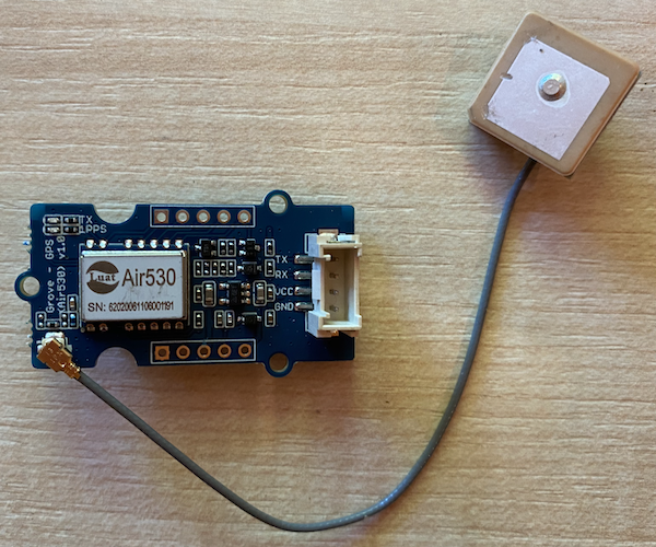
The sensor you'll use is a Grove GPS Air530 sensor. This sensor can connect to multiple GPS systems for a fast and accurate location fix. It consists of two parts: the core electronics of the sensor and an external antenna connected by a thin wire to receive radio signals from satellites.
This is a UART sensor, meaning it sends GPS data over UART.
Connect the GPS sensor
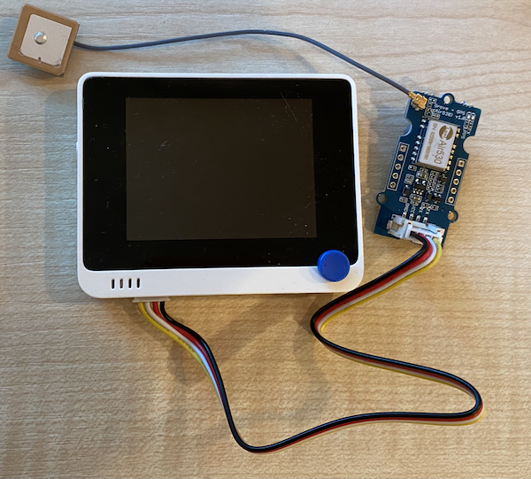
The Grove GPS sensor can be connected to the Wio Terminal.
Task - connect the GPS sensor
Connect the GPS sensor.
-
Insert one end of a Grove cable into the socket on the GPS sensor. It will only fit one way.
-
With the Wio Terminal disconnected from your computer or other power source, connect the other end of the Grove cable to the left-hand Grove socket on the Wio Terminal as you face the screen. This is the socket closest to the power button.
-
Position the GPS sensor so that the attached antenna has a clear view of the sky—ideally near an open window or outside. A clear signal is easier to achieve when there are no obstructions around the antenna.
-
You can now connect the Wio Terminal to your computer.
-
The GPS sensor has two LEDs: a blue LED that flashes when data is transmitted and a green LED that flashes every second when receiving data from satellites. Ensure the blue LED is flashing when you power up the Wio Terminal. After a few minutes, the green LED should start flashing. If it doesn't, you may need to reposition the antenna.
Program the GPS sensor
The Wio Terminal can now be programmed to use the connected GPS sensor.
Task - program the GPS sensor
Program the device.
-
Create a new Wio Terminal project using PlatformIO. Name this project
gps-sensor. Add code in thesetupfunction to configure the serial port. -
Add the following include directive to the top of the
main.cppfile. This includes a header file with functions to configure the left-hand Grove port for UART.#include <wiring_private.h> -
Below this, add the following line of code to declare a serial port connection to the UART port:
static Uart Serial3(&sercom3, PIN_WIRE_SCL, PIN_WIRE_SDA, SERCOM_RX_PAD_1, UART_TX_PAD_0); -
You need to add some code to redirect certain internal signal handlers to this serial port. Add the following code below the
Serial3declaration:void SERCOM3_0_Handler() { Serial3.IrqHandler(); } void SERCOM3_1_Handler() { Serial3.IrqHandler(); } void SERCOM3_2_Handler() { Serial3.IrqHandler(); } void SERCOM3_3_Handler() { Serial3.IrqHandler(); } -
In the
setupfunction, below where theSerialport is configured, configure the UART serial port with the following code:Serial3.begin(9600); while (!Serial3) ; // Wait for Serial3 to be ready delay(1000); -
Below this code in the
setupfunction, add the following code to connect the Grove pin to the serial port:pinPeripheral(PIN_WIRE_SCL, PIO_SERCOM_ALT); -
Add the following function before the
loopfunction to send the GPS data to the serial monitor:void printGPSData() { Serial.println(Serial3.readStringUntil('\n')); } -
In the
loopfunction, add the following code to read from the UART serial port and print the output to the serial monitor:while (Serial3.available() > 0) { printGPSData(); } delay(1000);This code reads from the UART serial port. The
readStringUntilfunction reads up to a terminator character, in this case, a new line. This will read an entire NMEA sentence (NMEA sentences are terminated with a new line character). While data can be read from the UART serial port, it is read and sent to the serial monitor via theprintGPSDatafunction. Once no more data can be read, theloopdelays for 1 second (1,000ms). -
Build and upload the code to the Wio Terminal.
-
Once uploaded, you can monitor the GPS data using the serial monitor.
> Executing task: platformio device monitor <

--- Available filters and text transformations: colorize, debug, default, direct, hexlify, log2file, nocontrol, printable, send_on_enter, time
--- More details at http://bit.ly/pio-monitor-filters
--- Miniterm on /dev/cu.usbmodem1201  9600,8,N,1 ---
--- Quit: Ctrl+C | Menu: Ctrl+T | Help: Ctrl+T followed by Ctrl+H ---
$GNGGA,020604.001,4738.538654,N,12208.341758,W,1,3,,164.7,M,-17.1,M,,*67
$GPGSA,A,1,,,,,,,,,,,,,,,*1E
$BDGSA,A,1,,,,,,,,,,,,,,,*0F
$GPGSV,1,1,00*79
$BDGSV,1,1,00*68
💁 You can find this code in the code-gps/wio-terminal folder.
😀 Your GPS sensor program was a success!
Disclaimer:
This document has been translated using the AI translation service Co-op Translator. While we aim for accuracy, please note that automated translations may include errors or inaccuracies. The original document in its native language should be regarded as the authoritative source. For critical information, professional human translation is advised. We are not responsible for any misunderstandings or misinterpretations resulting from the use of this translation.