8.2 KiB
Read GPS data - Raspberry Pi
In this part of the lesson, you will add a GPS sensor to your Raspberry Pi and read data from it.
Hardware
The Raspberry Pi requires a GPS sensor.
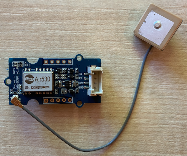
The sensor you'll use is a Grove GPS Air530 sensor. This sensor can connect to multiple GPS systems for a fast and accurate signal. It consists of two parts: the core electronics of the sensor and an external antenna connected by a thin wire to receive radio signals from satellites.
This is a UART sensor, meaning it transmits GPS data via UART.
Connect the GPS sensor
The Grove GPS sensor can be connected to the Raspberry Pi.
Task - Connect the GPS sensor
Connect the GPS sensor.
-
Insert one end of a Grove cable into the socket on the GPS sensor. It will only fit in one way.
-
With the Raspberry Pi powered off, connect the other end of the Grove cable to the UART socket labeled UART on the Grove Base Hat attached to the Pi. This socket is located in the middle row, on the side closest to the SD card slot, opposite the USB ports and Ethernet socket.
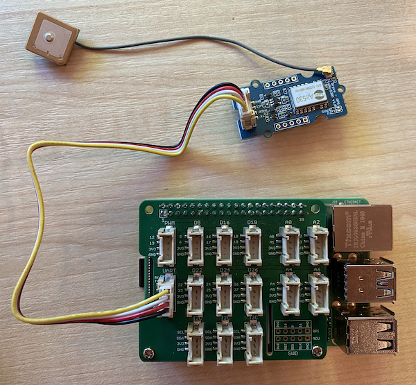
-
Position the GPS sensor so that the attached antenna has a clear view of the sky—ideally near an open window or outside. A clear signal is easier to achieve with no obstructions around the antenna.
Program the GPS sensor
The Raspberry Pi can now be programmed to use the connected GPS sensor.
Task - Program the GPS sensor
Program the device.
-
Power up the Pi and wait for it to boot.
-
The GPS sensor has two LEDs: a blue LED that flashes when data is transmitted and a green LED that flashes every second when receiving data from satellites. Ensure the blue LED is flashing when you power up the Pi. After a few minutes, the green LED should start flashing. If it doesn’t, you may need to reposition the antenna.
-
Launch VS Code, either directly on the Pi or by connecting via the Remote SSH extension.
⚠️ You can refer to the instructions for setting up and launching VS Code in lesson 1 if needed.
-
On newer Raspberry Pi models that support Bluetooth, there is a conflict between the serial port used for Bluetooth and the one used by the Grove UART port. To resolve this, follow these steps:
-
From the VS Code terminal, edit the
/boot/config.txtfile usingnano, a built-in terminal text editor, with the following command:sudo nano /boot/config.txtThis file cannot be edited directly in VS Code because it requires
sudopermissions (elevated privileges). VS Code does not run with these permissions. -
Use the arrow keys to navigate to the end of the file, then copy and paste the following code at the end:
dtoverlay=pi3-miniuart-bt
dtoverlay=pi3-disable-bt
enable_uart=1
You can paste using the standard keyboard shortcuts for your device (
Ctrl+von Windows, Linux, or Raspberry Pi OS,Cmd+von macOS). -
Save the file and exit nano by pressing
Ctrl+x. Pressywhen prompted to save the changes, then pressEnterto confirm overwriting/boot/config.txt.If you make a mistake, you can exit without saving and repeat these steps.
-
Edit the
/boot/cmdline.txtfile in nano with the following command:sudo nano /boot/cmdline.txt -
This file contains several key-value pairs separated by spaces. Remove any key-value pairs with the key
console. These entries will likely look like this:console=serial0,115200 console=tty1Use the arrow keys to navigate to these entries, then delete them using the
DelorBackspacekeys.For example, if your original file looks like this:
console=serial0,115200 console=tty1 root=PARTUUID=058e2867-02 rootfstype=ext4 elevator=deadline fsck.repair=yes rootwaitThe updated version will look like this:
root=PARTUUID=058e2867-02 rootfstype=ext4 elevator=deadline fsck.repair=yes rootwait -
Follow the same steps to save this file and exit nano.
-
Reboot your Pi, then reconnect to it in VS Code after it restarts.
-
-
From the terminal, create a new folder in the
piuser's home directory calledgps-sensor. Inside this folder, create a file namedapp.py. -
Open this folder in VS Code.
-
The GPS module sends UART data over a serial port. Install the
pyserialPip package to enable communication with the serial port in your Python code:pip3 install pyserial -
Add the following code to your
app.pyfile:import time import serial serial = serial.Serial('/dev/ttyAMA0', 9600, timeout=1) serial.reset_input_buffer() serial.flush() def print_gps_data(line): print(line.rstrip()) while True: line = serial.readline().decode('utf-8') while len(line) > 0: print_gps_data(line) line = serial.readline().decode('utf-8') time.sleep(1)This code imports the
serialmodule from thepyserialPip package. It then connects to the/dev/ttyAMA0serial port, which is the address of the serial port used by the Grove Pi Base Hat for its UART port. It also clears any existing data from this serial connection.Next, a function called
print_gps_datais defined to print the line passed to it to the console.The code then enters an infinite loop, reading as many lines of text as possible from the serial port during each iteration. It calls the
print_gps_datafunction for each line.After processing all the data, the loop pauses for one second before repeating.
-
Run this code. You will see raw output from the GPS sensor, which might look something like this:
$GNGGA,020604.001,4738.538654,N,12208.341758,W,1,3,,164.7,M,-17.1,M,,*67
$GPGSA,A,1,,,,,,,,,,,,,,,*1E
$BDGSA,A,1,,,,,,,,,,,,,,,*0F
$GPGSV,1,1,00*79
$BDGSV,1,1,00*68
If you encounter one of the following errors when stopping and restarting your code, add a
try - exceptblock to your while loop.UnicodeDecodeError: 'utf-8' codec can't decode byte 0x93 in position 0: invalid start byte UnicodeDecodeError: 'utf-8' codec can't decode byte 0xf1 in position 0: invalid continuation bytewhile True: try: line = serial.readline().decode('utf-8') while len(line) > 0: print_gps_data() line = serial.readline().decode('utf-8') # There's a random chance the first byte being read is part way through a character. # Read another full line and continue. except UnicodeDecodeError: line = serial.readline().decode('utf-8') time.sleep(1)
💁 You can find this code in the code-gps/pi folder.
😀 Congratulations! Your GPS sensor program is working successfully!
Disclaimer:
This document has been translated using the AI translation service Co-op Translator. While we strive for accuracy, please note that automated translations may contain errors or inaccuracies. The original document in its native language should be regarded as the authoritative source. For critical information, professional human translation is recommended. We are not responsible for any misunderstandings or misinterpretations resulting from the use of this translation.