
24 KiB
Capture audio - Wio Terminal
In this part of the lesson, you will write code to record audio on your Wio Terminal. The audio recording will be triggered by one of the buttons located on the top of the Wio Terminal.
Program the device to record audio
You can record audio from the microphone using C++ code. The Wio Terminal has only 192KB of RAM, which is insufficient for recording more than a few seconds of audio. However, it also has 4MB of flash memory, which can be used to store the recorded audio.
The built-in microphone captures an analog signal, which is converted into a digital signal that the Wio Terminal can process. When recording audio, the data must be captured at precise intervals—for example, to record audio at 16KHz, the audio must be sampled exactly 16,000 times per second, with equal spacing between each sample. Instead of relying on your code to handle this, you can use the direct memory access controller (DMAC). This hardware component can capture a signal and write it to memory without interrupting the processor's operations.
✅ Learn more about DMA on the direct memory access page on Wikipedia.
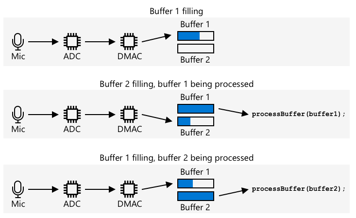
The DMAC can record audio from the ADC at fixed intervals, such as 16,000 times per second for 16KHz audio. It writes this data to a pre-allocated memory buffer, and when the buffer is full, it notifies your code to process the data. Using a single buffer can cause delays in recording, but you can set up multiple buffers. The DMAC writes to buffer 1, and when it’s full, it notifies your code to process buffer 1 while it writes to buffer 2. When buffer 2 is full, it notifies your code and switches back to buffer 1. As long as you process each buffer faster than the time it takes to fill one, no data will be lost.
Once each buffer is processed, the data can be written to flash memory. Flash memory requires specific addresses for writing, specifying where and how much data to write—similar to updating an array of bytes in memory. Flash memory has granularity, meaning erase and write operations must align with fixed sizes. For example, if the granularity is 4096 bytes and you request an erase at address 4200, it may erase all data from address 4096 to 8192. This means audio data must be written to flash memory in appropriately sized chunks.
Task - configure flash memory
-
Create a new Wio Terminal project using PlatformIO. Name the project
smart-timer. Add code in thesetupfunction to configure the serial port. -
Add the following library dependencies to the
platformio.inifile to enable access to the flash memory:lib_deps = seeed-studio/Seeed Arduino FS @ 2.1.1 seeed-studio/Seeed Arduino SFUD @ 2.0.2 -
Open the
main.cppfile and add the following include directive for the flash memory library at the top of the file:#include <sfud.h> #include <SPI.h>🎓 SFUD stands for Serial Flash Universal Driver, a library designed to work with various flash memory chips.
-
In the
setupfunction, add the following code to initialize the flash storage library:while (!(sfud_init() == SFUD_SUCCESS)) ; sfud_qspi_fast_read_enable(sfud_get_device(SFUD_W25Q32_DEVICE_INDEX), 2);This code loops until the SFUD library is initialized, then enables fast reads. The built-in flash memory can be accessed using a Queued Serial Peripheral Interface (QSPI), a type of SPI controller that allows continuous access via a queue with minimal processor usage. This makes reading and writing to flash memory faster.
-
Create a new file in the
srcfolder namedflash_writer.h. -
Add the following to the top of this file:
#pragma once

#include <Arduino.h>
#include <sfud.h>
This includes necessary header files, including the SFUD library header for interacting with flash memory.
-
Define a class in this new header file called
FlashWriter:class FlashWriter { public: private: }; -
In the
privatesection, add the following code:byte *_sfudBuffer; size_t _sfudBufferSize; size_t _sfudBufferPos; size_t _sfudBufferWritePos; const sfud_flash *_flash;This defines fields for the buffer used to store data before writing it to flash memory.
_sfudBufferis a byte array for temporary storage, and when it’s full, the data is written to flash memory._sfudBufferPostracks the current position in the buffer,_sfudBufferWritePostracks the position in flash memory, and_flashis a pointer to the flash memory—some microcontrollers have multiple flash memory chips. -
Add the following method to the
publicsection to initialize this class:void init() { _flash = sfud_get_device_table() + 0; _sfudBufferSize = _flash->chip.erase_gran; _sfudBuffer = new byte[_sfudBufferSize]; _sfudBufferPos = 0; _sfudBufferWritePos = 0; }This method configures the flash memory on the Wio Terminal for writing and sets up buffers based on the flash memory’s grain size. It’s placed in an
initmethod rather than a constructor because it must be called after the flash memory is initialized in thesetupfunction. -
Add the following code to the
publicsection:void writeSfudBuffer(byte b) { _sfudBuffer[_sfudBufferPos++] = b; if (_sfudBufferPos == _sfudBufferSize) { sfud_erase_write(_flash, _sfudBufferWritePos, _sfudBufferSize, _sfudBuffer); _sfudBufferWritePos += _sfudBufferSize; _sfudBufferPos = 0; } } void writeSfudBuffer(byte *b, size_t len) { for (size_t i = 0; i < len; ++i) { writeSfudBuffer(b[i]); } } void flushSfudBuffer() { if (_sfudBufferPos > 0) { sfud_erase_write(_flash, _sfudBufferWritePos, _sfudBufferSize, _sfudBuffer); _sfudBufferWritePos += _sfudBufferSize; _sfudBufferPos = 0; } }This code defines methods for writing bytes to the flash storage system. It writes data to an in-memory buffer sized for the flash memory, and when the buffer is full, it writes the data to flash memory, erasing any existing data at that location. The
flushSfudBuffermethod writes incomplete buffers, as the captured data won’t always be exact multiples of the grain size.💁 The final portion of the data may include extra unwanted bytes, but this is acceptable since only the necessary data will be read later.
Task - set up audio capture
-
Create a new file in the
srcfolder namedconfig.h. -
Add the following to the top of this file:
#pragma once

#define RATE 16000
#define SAMPLE_LENGTH_SECONDS 4
#define SAMPLES RATE * SAMPLE_LENGTH_SECONDS
#define BUFFER_SIZE (SAMPLES * 2) + 44
#define ADC_BUF_LEN 1600
This code defines constants for audio capture.
Constant Value Description RATE 16000 The sample rate for the audio. 16,000 is 16KHz SAMPLE_LENGTH_SECONDS 4 The duration of audio to record. Set to 4 seconds. Increase this value to record longer audio. SAMPLES 64000 The total number of audio samples to capture. Calculated as the sample rate multiplied by the duration in seconds. BUFFER_SIZE 128044 The size of the audio buffer. Audio will be stored as a WAV file, which includes a 44-byte header followed by 128,000 bytes of audio data (each sample is 2 bytes). ADC_BUF_LEN 1600 The size of the buffers used to capture audio from the DMAC. 💁 If 4 seconds is too short for your timer, you can increase the
SAMPLE_LENGTH_SECONDSvalue, and all other values will adjust accordingly. -
Create a new file in the
srcfolder namedmic.h. -
Add the following to the top of this file:
#pragma once

#include <Arduino.h>

#include "config.h"
#include "flash_writer.h"
This includes necessary header files, including
config.handFlashWriter. -
Add the following to define a
Micclass for capturing audio from the microphone:class Mic { public: Mic() { _isRecording = false; _isRecordingReady = false; } void startRecording() { _isRecording = true; _isRecordingReady = false; } bool isRecording() { return _isRecording; } bool isRecordingReady() { return _isRecordingReady; } private: volatile bool _isRecording; volatile bool _isRecordingReady; FlashWriter _writer; }; Mic mic;This class includes fields to track whether recording has started and whether the recording is ready for use. The DMAC continuously writes to memory buffers, so the
_isRecordingflag determines whether these should be processed or ignored. The_isRecordingReadyflag is set when the required 4 seconds of audio have been captured. The_writerfield is used to save audio data to flash memory.A global variable is declared for an instance of the
Micclass. -
Add the following code to the
privatesection of theMicclass:typedef struct { uint16_t btctrl; uint16_t btcnt; uint32_t srcaddr; uint32_t dstaddr; uint32_t descaddr; } dmacdescriptor; // Globals - DMA and ADC volatile dmacdescriptor _wrb[DMAC_CH_NUM] __attribute__((aligned(16))); dmacdescriptor _descriptor_section[DMAC_CH_NUM] __attribute__((aligned(16))); dmacdescriptor _descriptor __attribute__((aligned(16))); void configureDmaAdc() { // Configure DMA to sample from ADC at a regular interval (triggered by timer/counter) DMAC->BASEADDR.reg = (uint32_t)_descriptor_section; // Specify the location of the descriptors DMAC->WRBADDR.reg = (uint32_t)_wrb; // Specify the location of the write back descriptors DMAC->CTRL.reg = DMAC_CTRL_DMAENABLE | DMAC_CTRL_LVLEN(0xf); // Enable the DMAC peripheral DMAC->Channel[1].CHCTRLA.reg = DMAC_CHCTRLA_TRIGSRC(TC5_DMAC_ID_OVF) | // Set DMAC to trigger on TC5 timer overflow DMAC_CHCTRLA_TRIGACT_BURST; // DMAC burst transfer _descriptor.descaddr = (uint32_t)&_descriptor_section[1]; // Set up a circular descriptor _descriptor.srcaddr = (uint32_t)&ADC1->RESULT.reg; // Take the result from the ADC0 RESULT register _descriptor.dstaddr = (uint32_t)_adc_buf_0 + sizeof(uint16_t) * ADC_BUF_LEN; // Place it in the adc_buf_0 array _descriptor.btcnt = ADC_BUF_LEN; // Beat count _descriptor.btctrl = DMAC_BTCTRL_BEATSIZE_HWORD | // Beat size is HWORD (16-bits) DMAC_BTCTRL_DSTINC | // Increment the destination address DMAC_BTCTRL_VALID | // Descriptor is valid DMAC_BTCTRL_BLOCKACT_SUSPEND; // Suspend DMAC channel 0 after block transfer memcpy(&_descriptor_section[0], &_descriptor, sizeof(_descriptor)); // Copy the descriptor to the descriptor section _descriptor.descaddr = (uint32_t)&_descriptor_section[0]; // Set up a circular descriptor _descriptor.srcaddr = (uint32_t)&ADC1->RESULT.reg; // Take the result from the ADC0 RESULT register _descriptor.dstaddr = (uint32_t)_adc_buf_1 + sizeof(uint16_t) * ADC_BUF_LEN; // Place it in the adc_buf_1 array _descriptor.btcnt = ADC_BUF_LEN; // Beat count _descriptor.btctrl = DMAC_BTCTRL_BEATSIZE_HWORD | // Beat size is HWORD (16-bits) DMAC_BTCTRL_DSTINC | // Increment the destination address DMAC_BTCTRL_VALID | // Descriptor is valid DMAC_BTCTRL_BLOCKACT_SUSPEND; // Suspend DMAC channel 0 after block transfer memcpy(&_descriptor_section[1], &_descriptor, sizeof(_descriptor)); // Copy the descriptor to the descriptor section // Configure NVIC NVIC_SetPriority(DMAC_1_IRQn, 0); // Set the Nested Vector Interrupt Controller (NVIC) priority for DMAC1 to 0 (highest) NVIC_EnableIRQ(DMAC_1_IRQn); // Connect DMAC1 to Nested Vector Interrupt Controller (NVIC) // Activate the suspend (SUSP) interrupt on DMAC channel 1 DMAC->Channel[1].CHINTENSET.reg = DMAC_CHINTENSET_SUSP; // Configure ADC ADC1->INPUTCTRL.bit.MUXPOS = ADC_INPUTCTRL_MUXPOS_AIN12_Val; // Set the analog input to ADC0/AIN2 (PB08 - A4 on Metro M4) while (ADC1->SYNCBUSY.bit.INPUTCTRL) ; // Wait for synchronization ADC1->SAMPCTRL.bit.SAMPLEN = 0x00; // Set max Sampling Time Length to half divided ADC clock pulse (2.66us) while (ADC1->SYNCBUSY.bit.SAMPCTRL) ; // Wait for synchronization ADC1->CTRLA.reg = ADC_CTRLA_PRESCALER_DIV128; // Divide Clock ADC GCLK by 128 (48MHz/128 = 375kHz) ADC1->CTRLB.reg = ADC_CTRLB_RESSEL_12BIT | // Set ADC resolution to 12 bits ADC_CTRLB_FREERUN; // Set ADC to free run mode while (ADC1->SYNCBUSY.bit.CTRLB) ; // Wait for synchronization ADC1->CTRLA.bit.ENABLE = 1; // Enable the ADC while (ADC1->SYNCBUSY.bit.ENABLE) ; // Wait for synchronization ADC1->SWTRIG.bit.START = 1; // Initiate a software trigger to start an ADC conversion while (ADC1->SYNCBUSY.bit.SWTRIG) ; // Wait for synchronization // Enable DMA channel 1 DMAC->Channel[1].CHCTRLA.bit.ENABLE = 1; // Configure Timer/Counter 5 GCLK->PCHCTRL[TC5_GCLK_ID].reg = GCLK_PCHCTRL_CHEN | // Enable peripheral channel for TC5 GCLK_PCHCTRL_GEN_GCLK1; // Connect generic clock 0 at 48MHz TC5->COUNT16.WAVE.reg = TC_WAVE_WAVEGEN_MFRQ; // Set TC5 to Match Frequency (MFRQ) mode TC5->COUNT16.CC[0].reg = 3000 - 1; // Set the trigger to 16 kHz: (4Mhz / 16000) - 1 while (TC5->COUNT16.SYNCBUSY.bit.CC0) ; // Wait for synchronization // Start Timer/Counter 5 TC5->COUNT16.CTRLA.bit.ENABLE = 1; // Enable the TC5 timer while (TC5->COUNT16.SYNCBUSY.bit.ENABLE) ; // Wait for synchronization } uint16_t _adc_buf_0[ADC_BUF_LEN]; uint16_t _adc_buf_1[ADC_BUF_LEN];This code defines a
configureDmaAdcmethod to configure the DMAC, connecting it to the ADC and setting it to alternate between two buffers,_adc_buf_0and_adc_buf_1.💁 Microcontroller development often involves complex code to interact directly with hardware. This code is more intricate than what you’d write for a single-board computer or desktop computer, as there’s no operating system to assist. Some libraries can simplify this, but the complexity remains.
-
Below this, add the following code:
// WAV files have a header. This struct defines that header
struct wavFileHeader
{
    char riff[4];         /* "RIFF"                                  */
    long flength;         /* file length in bytes                    */
    char wave[4];         /* "WAVE"                                  */
    char fmt[4];          /* "fmt "                                  */
    long chunk_size;      /* size of FMT chunk in bytes (usually 16) */
    short format_tag;     /* 1=PCM, 257=Mu-Law, 258=A-Law, 259=ADPCM */
    short num_chans;      /* 1=mono, 2=stereo                        */
    long srate;           /* Sampling rate in samples per second     */
    long bytes_per_sec;   /* bytes per second = srate*bytes_per_samp */
    short bytes_per_samp; /* 2=16-bit mono, 4=16-bit stereo          */
    short bits_per_samp;  /* Number of bits per sample               */
    char data[4];         /* "data"                                  */
    long dlength;         /* data length in bytes (filelength - 44)  */
};

void initBufferHeader()
{
    wavFileHeader wavh;

    strncpy(wavh.riff, "RIFF", 4);
    strncpy(wavh.wave, "WAVE", 4);
    strncpy(wavh.fmt, "fmt ", 4);
    strncpy(wavh.data, "data", 4);

    wavh.chunk_size = 16;
    wavh.format_tag = 1; // PCM
    wavh.num_chans = 1;  // mono
    wavh.srate = RATE;
    wavh.bytes_per_sec = (RATE * 1 * 16 * 1) / 8;
    wavh.bytes_per_samp = 2;
    wavh.bits_per_samp = 16;
    wavh.dlength = RATE * 2 * 1 * 16 / 2;
    wavh.flength = wavh.dlength + 44;

    _writer.writeSfudBuffer((byte *)&wavh, 44);
}
This code defines the WAV header as a 44-byte struct. It writes details about the audio file’s rate, size, and number of channels. This header is then written to flash memory.
-
Below this code, add the following to declare a method for processing audio buffers:
void audioCallback(uint16_t *buf, uint32_t buf_len)
{
    static uint32_t idx = 44;

    if (_isRecording)
    {
        for (uint32_t i = 0; i < buf_len; i++)
        {
            int16_t audio_value = ((int16_t)buf[i] - 2048) * 16;

            _writer.writeSfudBuffer(audio_value & 0xFF);
            _writer.writeSfudBuffer((audio_value >> 8) & 0xFF);
        }

        idx += buf_len;

        if (idx >= BUFFER_SIZE)
        {
            _writer.flushSfudBuffer();
            idx = 44;
            _isRecording = false;
            _isRecordingReady = true;
        }
    }
}
The audio buffers are arrays of 16-bit integers containing audio data from the ADC. The ADC returns 12-bit unsigned values (0–1023), which must be converted to 16-bit signed values and then into 2-byte raw binary data.
These bytes are written to flash memory buffers, starting at index 44 (offset for the WAV file header). Once the required audio length is captured, the remaining data is written to flash memory.
-
In the
publicsection of theMicclass, add the following code:void dmaHandler() { static uint8_t count = 0; if (DMAC->Channel[1].CHINTFLAG.bit.SUSP) { DMAC->Channel[1].CHCTRLB.reg = DMAC_CHCTRLB_CMD_RESUME; DMAC->Channel[1].CHINTFLAG.bit.SUSP = 1; if (count) { audioCallback(_adc_buf_0, ADC_BUF_LEN); } else { audioCallback(_adc_buf_1, ADC_BUF_LEN); } count = (count + 1) % 2; } }This code is called by the DMAC to notify your program when buffers are ready for processing. It checks for data and calls the
audioCallbackmethod with the relevant buffer. -
Outside the class, after the
Mic mic;declaration, add the following code:void DMAC_1_Handler() { mic.dmaHandler(); }The
DMAC_1_Handlerfunction is called by the DMAC when buffers are ready for processing. This function is identified by name and doesn’t require explicit registration. -
Add the following two methods to the
publicsection of theMicclass:void init() { analogReference(AR_INTERNAL2V23); _writer.init(); initBufferHeader(); configureDmaAdc(); } void reset() { _isRecordingReady = false; _isRecording = false; _writer.reset(); initBufferHeader(); }The
initmethod initializes theMicclass. It sets the correct voltage for the microphone pin, initializes the flash memory writer, writes the WAV file header, and configures the DMAC. Theresetmethod clears the flash memory and rewrites the header after the audio has been processed.
Task - record audio
-
In the
main.cppfile, add an include directive for themic.hheader file:#include "mic.h" -
In the
setupfunction, initialize the C button. Audio recording will start when this button is pressed and continue for 4 seconds:pinMode(WIO_KEY_C, INPUT_PULLUP); -
Below this, initialize the microphone and print a message to the console indicating that audio is ready to be recorded:
mic.init(); Serial.println("Ready."); -
Above the
loopfunction, define a function to process the recorded audio. For now, this function does nothing, but later in the lesson, it will send the audio for speech-to-text conversion:void processAudio() { } -
Add the following to the
loopfunction:void loop() { if (digitalRead(WIO_KEY_C) == LOW && !mic.isRecording()) { Serial.println("Starting recording..."); mic.startRecording(); } if (!mic.isRecording() && mic.isRecordingReady()) { Serial.println("Finished recording"); processAudio(); mic.reset(); } }This code checks the C button, and if it’s pressed and recording hasn’t started, the
_isRecordingfield of theMicclass is set to true. This causes theaudioCallbackmethod to store audio until 4 seconds have been captured. Once the recording is complete,_isRecordingis set to false, and_isRecordingReadyis set to true. Theloopfunction then checks this flag, calls theprocessAudiofunction, and resets theMicclass. -
Build the code, upload it to your Wio Terminal, and test it using the serial monitor. Press the C button (the leftmost button near the power switch) and speak. The device will record 4 seconds of audio.
--- Available filters and text transformations: colorize, debug, default, direct, hexlify, log2file, nocontrol, printable, send_on_enter, time
--- More details at http://bit.ly/pio-monitor-filters
--- Miniterm on /dev/cu.usbmodem1101  9600,8,N,1 ---
--- Quit: Ctrl+C | Menu: Ctrl+T | Help: Ctrl+T followed by Ctrl+H ---
Ready.
Starting recording...
Finished recording
💁 You can find this code in the code-record/wio-terminal folder. Your audio recording program was a success!
Disclaimer:
This document has been translated using the AI translation service Co-op Translator. While we aim for accuracy, please note that automated translations may include errors or inaccuracies. The original document in its native language should be regarded as the authoritative source. For critical information, professional human translation is advised. We are not responsible for any misunderstandings or misinterpretations resulting from the use of this translation.